CAMERA MODEL
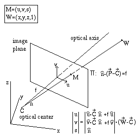
 The pinhole camera model assumes that the 3D scene is mapped
on the image plane with a central projection throught the
optical center, C (figure on the right).
The image plane is the plane orthogonal to
the optical axis (straight line through the optical center
c with direction n).
A point W, with space coordinates w=(x,y,z),
is projected in the image plane on the point M,
with image-plane coordinates m=(u,v).
In cartesian coordinates the projection is
(u, v, and n are a unit coordinate triplet)
u = u c + f u (w - c) /
[ n (w - c) ]
v = v c + f v (w - c) /
[ n (w - c) ]
In projective coordinates this transformation is a linear map
(see figure).
The camera is thus modeled as a perspective projection matrix P
that can be factorized as P=A [R | t],
where R is a rotation matrix, and t a translation vector,
that bring the camera frame in the world frame.
The matrix A describes the intrinsic parameters of the camera,
uo and vo are the coordinate
of the principal point (intersection of the optical axis and image
plane) and can be set to 0. g is a skew factor that model
for non-orthogonal u, v axes. If these are
orthogonal g=0.
We write the matrix P in the form
P = [ Q | q ]
where q = - Q c.
The optical ray of a point M is
w = c + t Q-1 m
Epipolar lines
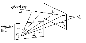
 If we have two cameras imaging the scene (ie, a stereo pair)
all the points on an optical ray of the first camera lay on a line
in the image plane of the second camera. This is called the
epipolar line of the point M1 (intersection
of the optical ray and the image plane of the first camera).
All the epipolar lines in the image plane of the second camera pass
through one point, namely the point of intersection of the image plane
with the line joining the centers of the two cameras (see figure).
Therefore the epipolar lines form a bundle.
The center of the bundle is called epipole.
Rectification
Any stereo pair of images can be transformed so that the epipolar
lines are parallel and horizontal in each image.
This is called rectification and amounts to siutably rotate
the optical axes making them parallel, and orthogonal to the line
joining the two camera centers.
Let P' denote the new imaging map. Since the two optical axes
are parallel, and supposing that the cameras have the same intrinsic
parameters, we can write
P'1 =
A [ R' | -R' c1 ]
P'2 =
A [ R' | -R' c2 ]
where the rotation R' is [r1, r2,
r3]t, with
- r1 being the unit vector of the line joining the two
camera centers,
(c1 - c2) /
|c1 - c2|
- r2 a unit vector orthogonal to r1
- and r3 = r1 x r2
The rectification is thus the trasformation that maps the images into
rectified images that would be obtained in the rectified geometry
(ie, when the image planes are coplanar and parallel to the line
joining the two centers).
The equations of an optical ray in the original and in the rectified
geometry are
w =
ci
+ t'i Q'-1 m'i
w =
ci
+ ti Qi-1 mi
therefore the rectification transformation is, up to a scale factor t,
m'i = t Q' Qi-1
mi
Marco Corvi - Page hosted by
geocities.com.
 The pinhole camera model assumes that the 3D scene is mapped
on the image plane with a central projection throught the
optical center, C (figure on the right).
The image plane is the plane orthogonal to
the optical axis (straight line through the optical center
c with direction n).
 If we have two cameras imaging the scene (ie, a stereo pair)
all the points on an optical ray of the first camera lay on a line
in the image plane of the second camera. This is called the
epipolar line of the point M1 (intersection
of the optical ray and the image plane of the first camera).